Automated Load Transfer from Two-Way Slab Panels to Supporting Beams
Hello Seán,
I joined this course specifically to gain a clear and practical understanding of how loads from slab panels are transferred to supporting beams, particularly for one-way and two-way slab behavior. While the course has been extremely helpful overall, I’m still struggling to clearly resolve this specific aspect and would really appreciate your guidance.
From standard references (e.g., Reynolds & Steedman), the load carried by beams supporting a slab panel can be estimated using:
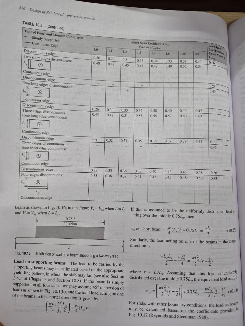
45° load dispersion for slabs supported on all four sides, and
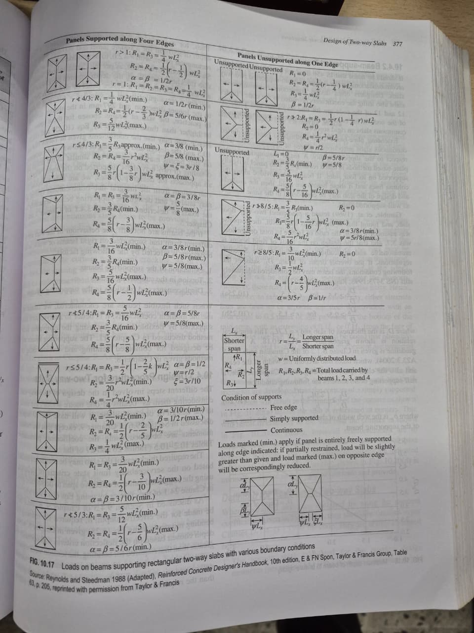
Coefficient-based formulations (R₁–R₄, α, β, ψ) for panels with various combinations of continuous, simply supported, or discontinuous edges (as shown in the attached figures).
In these formulations:
Loads on beams depend on the aspect ratio ( r = L_y / L_x ),
The support condition of each edge, and
Whether the slab behaves predominantly as one-way or two-way.
Loads on beam also depends on conditions of supports(whether edge is free, continuous or simply supported.
Objective
My objective is to automate this slab-to-beam load calculation using only geometric and connectivity data.
Data Structure
Nodes (JSON)
Node IDs with corresponding (X, Y, Z) coordinates
Elements (JSON)
Slab and beam connectivity defined using node IDs
Intended Workflow
Identify slab panels and compute spans ( L_x, L_y ) from node coordinates
Classify slab panels as one-way or two-way based on span ratio and edge restraints
Identify the support condition of each slab edge (continuous / discontinuous / free) from beam connectivity
Compute the total load carried by each supporting beam using:
45° dispersion where applicable, or
Coefficient-based expressions (R₁–R₄) from the attached tables
For internal beams, accumulate load contributions from adjacent slab panels on both sides
Convert the resulting load into an equivalent uniformly distributed load (UDL)
Store this UDL directly in the beam element definition (e.g., adding a UDL key in the elements JSON)
Questions
Is this coefficient-based slab-to-beam load transfer consistent with the plate assumptions used in the course?
Would you recommend applying these tabulated formulations directly for automation, or is there a more FEM-consistent approach when beams and slabs are modeled separately?
In practice, how should the transition between one-way and two-way slab behavior be handled robustly in an automated workflow?
Attachments
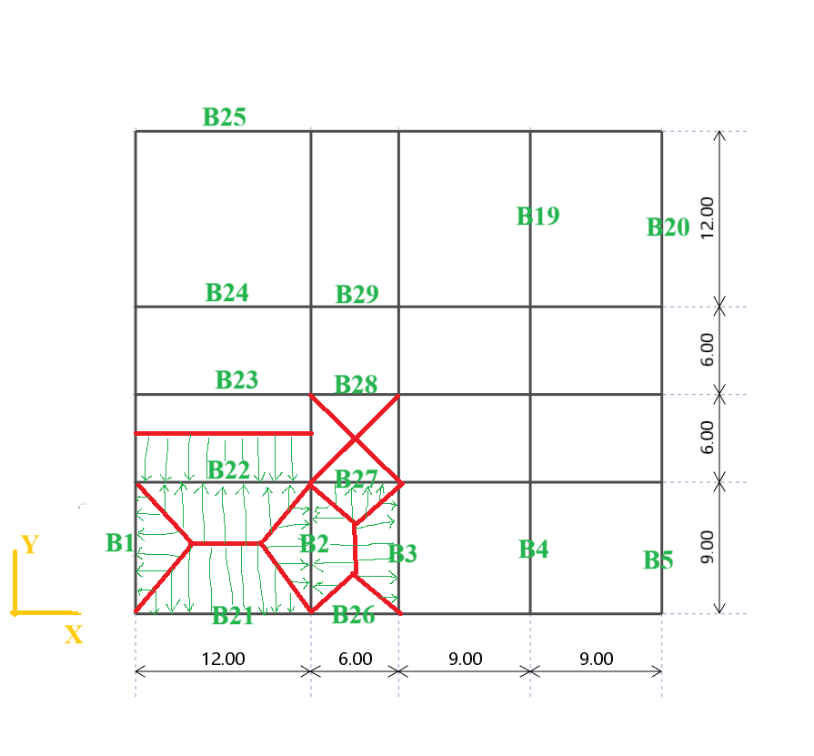
Schematics illustrating slab panels and internal beams receiving load from adjacent panels
Textbook figures showing load dispersion and coefficient-based formulations
Node and element JSON files describing the model geometry and connectivity
I would be very grateful for any guidance or direction you can provide on this topic.
I am posting here again as it has been over a month since my original inquiry regarding Automated Load Transfer (posted on [Dec 17, 2025]).
I joined this course specifically because it was promoted as a resource for ‘clear and practical understanding’ with instructor support. However, despite being a paying student, I have received no guidance on this critical technical hurdle for over four weeks.
As many here are likely using this course to bridge the gap between theory and automation, I believe a response to these types of structural logic questions is essential to the value of the program. I would appreciate it if the team could prioritize a reply so I can move forward with my workflow.