Questions and discussion for this lecture live here. Fire away by hitting Reply below ![]()
Dear Sean,
When we analyse symmetrical beams, this method holds (product moment of inertia Izy = 0). But what if we have asymmetrical cross sections (Izy is not equal to 0)? Bending moments in the z-direction causes the entire beam to also bend in the y-direction. How can we implement this in our 3D beam stiffness matrix? Will this also effect our tranformation matrix?
Kind regards,
Yannick
Hey @Yannick,
Once you provide the correct values for the moments of inertia for your section, Ixx, Iyy and Ixy, the stiffness matrix should accurately represent the flexural and torsional behaviour of the element.
One detail to be aware of is that we are assuming no coupling between actions - so-called ‘cross-axis coupling’. Refer to lecture 5 at about the 05:00 mark when i mention this.
Seán
Hi Sean,
Okay, that is indeed true. But what if we do have coupling? Will the matrix [B] for bending around the y-axis be extended with the [B] matrix from the bending around the z-axis because of the fact it is coupled?
z * [B] from bending around y-axis in the z-direction (u_z1, phi_y1, u_z2, phi_y2):

y * [B] from bending around z-axis in the y-direction (u_y1, phi_z1, u_y2, phi_z2):

[B] combined (u_y1, u_z1, phi_y1, phi_z1, u_y2, u_z2, phi_y2, phi_z2):
Now applying the minimal potential energy method to find the stiffness matrix, we do find the following relation:

Multiplying [B]^T[C][B], integrating over the volume and adding the terms for u_x and phi_z, we will get the following local stiffness matrix [K_L]:

This matrix is identical to the ones derived from the lectures but now we have extra terms for the coupling effect, but I was wondering if this is the correct way of adding the coupling effect.
Hey @Yannick, I’m afraid without more research at this end I cannot confirm with any great authority that this is the appropriate approach to take…we’re getting into more specialist analysis now.
Sorry I can’t provide you with a more satisfying answer than that!
As a next step, I would direct you to a great text on this called, Matrix Structural Analysis by McGuire, Gallagher and Ziemian. This is a very under-rated but in my view, exceptional reference text on all things related to the topic. You’re likely to find a fruitful avenue for further investigation in there. If you do…come back and let us know how you faired!
S
Hello Sean,
It’s been a while, but I made a study arround this subject. This time I approached the problem fully analytical and I got some very nice results to share with you.
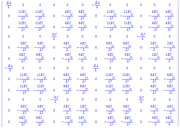
The new 3D beam stiffness matrix for a beam element is the following:
This stiffness matrix accounts for non-symmetrical cross-sections and also for shear center offset. This creates the non-diagonal terms because of coupling.
If interested I can also show an even more advanced stiffness matrix for beam elements accounting for shear deformation, construction line offset and warping. This is a 14x14 beam matrix and is really complex, but is fully usable.
Yannick
edit: Notice that when you set EI__yz = 0, e_y = 0 and e_z = 0, the stiffness matrix will become the original 3D beam stiffness matrix arrived with the shape functions.
@Yannick - apologies for the delay in replying!
You have been busy!! This is a really nice piece of work. Would you be willing to write it up in ‘tutorial’ format in an article for ES? I’m sure readers (myself included) would very much like you to walk us through this!
S

