Questions and discussion for this lecture live here. Fire away by hitting Reply below ![]()
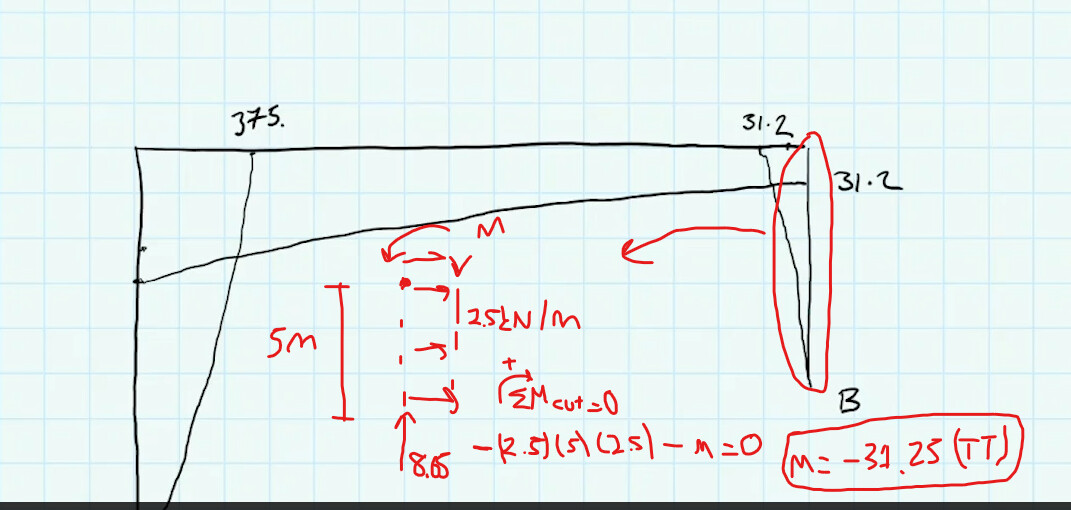
Hello Sean at video 12:54, the right substructure shall have tension top right ? ( i mean leftwards is tension for this substructure). from middle substructure to right substructure moment is changing from +31.25 KN.m to -31.25 KN.m. The numerical value is still continuous just changing the sign. Am i missing something ? Could you please check my figure above for the right substructure ?
Maybe my confusion arises from this fundamental question :
When we are drawing the Normal Force and Shear Force diagrams we are using Deformation Sign Convention where clockwise moment creating shear direction is positive and upwards is positive for normal force. However, for moment we need to draw positive or negative based on where tension is. If we assume that moment creating tension under each substructure for this frame as positive, actually all of the segments have positive moment as you said. Maybe it is the confused part for me ?
I would be grateful whenever you may help.
Cheers,
Burak
The BMD correctly shows tension on the left side of the right-hand column. Looking at your image, when you isolate the right column and consider moment equilibrium of it, you assume a counter-clockwise moment (nothing wrong with this). However, this then evaluates to a negative number (-31.25 kNm). This tells us that the orientation you assumed was not correct and in fact the internal moment acts in the opposite direction (clockwise). This will induce tension on the inside (left) face of the right-hand column, as shown.
BTW, I just recently updated this article and added more video walkthrough examples - you may find this helpful…
https://www.engineeringskills.com/posts/shear-and-moment-diagrams
Seán
1 Like
Thanks a lot Sean, i guess after struggling and making mistakes, the blur is getting clearer. As you said, exactly it is - value means TT so the diagram makes sense.
1 Like