Questions and discussion for this lecture live here. Fire away by hitting Reply below ![]()
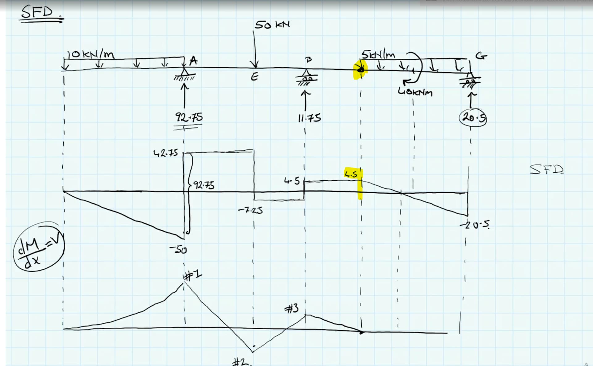
When you draw shear force diagram you did not consider hinge 4.5 KN? Is it becausw the two parta cancel each other?
Good question - remember that this is a rotational hinge so it allows the transmission of force (not moment). This means that it has no impact on the shear force diagram and for the purposes of drawing the shear force diagram, it may as well not exist.
Seán
1 Like
Hello Sean, i guess it is almost same question but with different perspective maybe not sure : Technically speaking, we can almost say that these LHS of the rotational hinge and RHS of the rotational hinge are different “sub-structures” (not structures because it is still one system, but they are actually only bonded by the rotational hinge) which means that as @petrasvestartas noted these forces are cancelling out in the global manner, but if we separeted these sub structures through the hinge of course we would expose these Vf forces and these Vf forces would make the shear force at the hinge equals to 0 (from LHS) and then again 4.5 to upwards (Vf from RHS) while drawing the overall SFD for the whole structure. Is it the correct interpretation ?
Thanks a lot,
Burak
Hi @m.burakcakir33 - when we cut the structure at the hinge, we reveal the internal shear force at that location…just like we would if we cut the structure at any other location. Remember, in the context of shear forces, the rotational hinge has not impact - it’s just like cutting the structure and revealing the internal shear force at any other location.
So, when we cut the structure (at the hinge or any other location) we reveal the internal shear forces on either side of the cut. On one side, the shear force will act down (depending on the sign of the shear force at that point in the structure) and on the other side of the cut, the shear will act up…but remember, these two forces are just different representations of the same shear force at that location. They are not two different shear forces that cancel each other out, although it is tempting to view them as such since the force arrows point in opposite directions - but this is just a consequence of our shear force sign convention. Review lectures 17 and 18 again for deeper discussion of this.
1 Like
Thank you very much for the answer Sean, it is crystal clear right now.
1 Like
Hey, Dr Sean, just a heads up on this one. I always try and do the problem as soon as the video starts to make sure I understand the problem myself (as one should), but ran into a little snag. At the start of the video, the 5 kN/m was not given, so I assumed that, due to scale of the UDL magnitudes in the initial image, that 10 kN/m was the UDL on the right side after the pin. I solved that problem well enough, but found out later that the number was supposed to be 5kN/m for that portion of the load.
All good, still got the practice in. ![]() But if you could, please overlay the 5 kN/m UDL on the right hand side so one can still complete to the similar solution you get. I am going to move on and call it good after having checked that the approaches were similar.
But if you could, please overlay the 5 kN/m UDL on the right hand side so one can still complete to the similar solution you get. I am going to move on and call it good after having checked that the approaches were similar.
1 Like