Questions and discussion for this lecture live here. Fire away by hitting Reply below ![]()
Hello Sean,
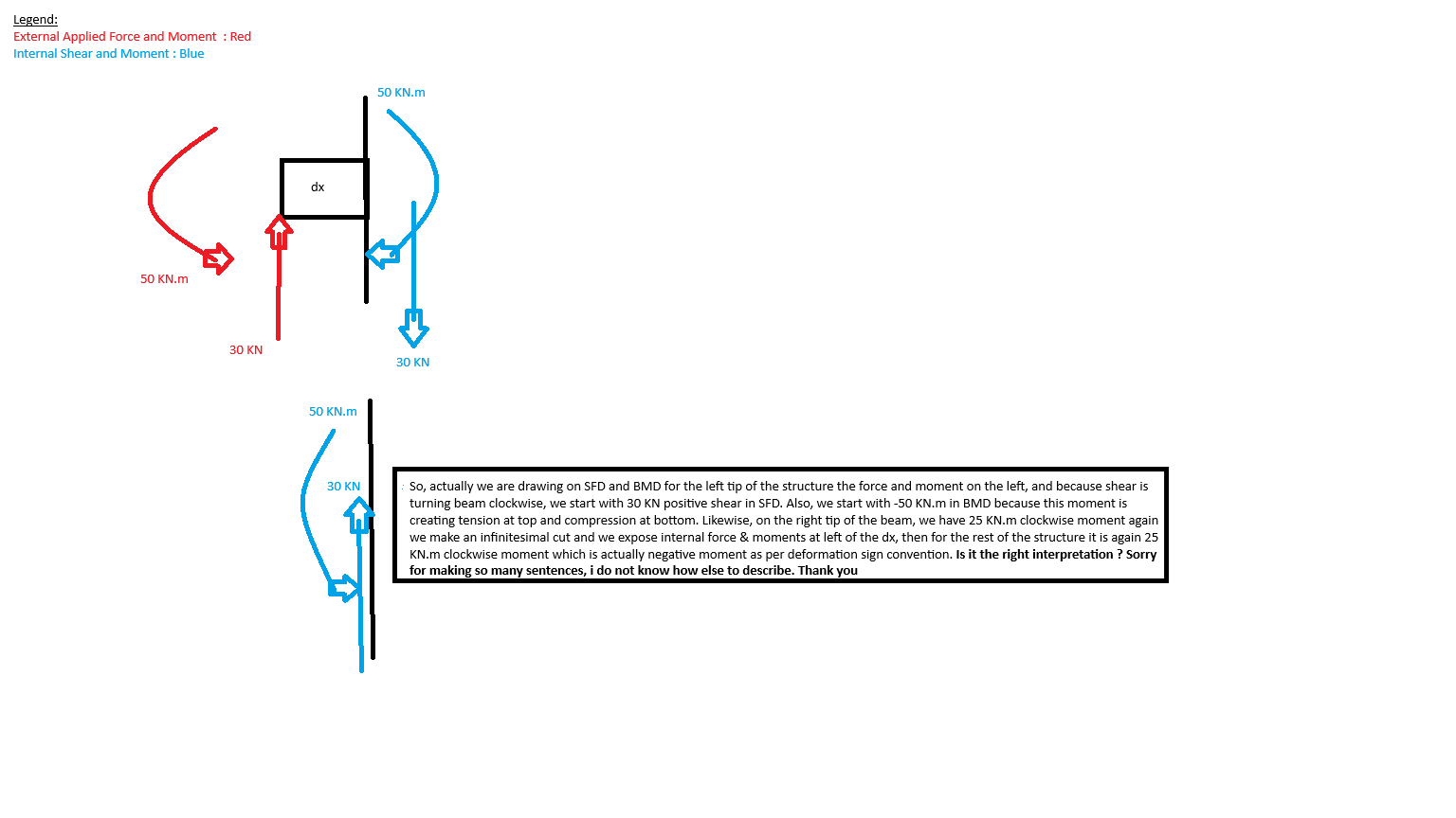
In video 19:00 - 19:11 range or as can be seen in screenshot, i just wanted to clarify bulletpoints as mentioned below whether i understood correctly or not ;
1- SFD and BMD are drawn based on deformation sign convention. Therefore, we will draw our graphs based on this sign convention’s lead i.e if we have clockwise moment of 50 KN.m at point x=5, that means we shall draw in BMD as -50 KN.m
2- Normally in previous examples, we used deformation sign convention signs for moment and shear, but for this example between 19:00 - 19:11, we state Mcut as clockwise moment (logically to balance the left moment), and because the value come up positive with this assumption which is the inverse of deformation sign convention we stated as - value in BMD.
Can we simplify the sign convention as below :
1- if we have a cut, use deformation sign convention to state internal moment and shear forces and we are drawing SFD and BMD totally for internal forces or in other words the reaction of the system purely, but we have to use static sign convention for the cuts equlibrium to ensure system is static.
Therefore, clockwise moments and upwards shear are positive. Considering these, if we got a negative value from static sign convention equation for Minternal and Vinternal that shall mean that we shall have negative values for Minternal and Vinternal in SFD and BMD. However, if we have a positive values for them, that means our deformation sign convention sign assumptions were correct, and we can directly treat them as postiive values in SFD and BMD.
Sorry for huge explanation and question Sean, i do not know how else to explain it. It is very crucial point for understanding and i want to make it right.
Thanks a lot in advance,
Thanks for your time.
Burak
Hie Sean ,
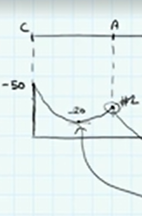
Wanted some clarity i am bit confused why is it that we have established (with reference to the image) that -20knm causes tension on top and compression at the bottom why is it that the shape of the BM the curves , curves downward like a cup , and is not inverted with the respect to how it is drawn in the picture
Hey - the shape of the BMD follows on directly from the shape of the shear force diagram - by this, I mean that we can infer directly from the shape of the SFD that the bending moment diagram is shaped as shown. It stems from the differential relationship between shear and moment…
dM/dx = V
This tells us that the slope of the BMD is equal to the SF at a point. Now, if we look at the SFD, we see that at C it is positive but reducing linearly as we move towards A. This means that the slope of the BMD is also positive and reducing linearly. Since the BM at C is negative 50 kNm (above the line since BMD is positive downward) - this gives us the ‘cup’ shape shown. The local minimum is also identified where the SF is zero.
The crux of this is that we have a moment applied at C which means the BMD starts off above the line rather than at zero which is what we’re more used to seeing at the free end of a cantilever. As a result, the BMD appears as a cup since it is above the line as-opposed to below the line which is what we see more often in this case.
I hope that helps clear this up.
BTM - I recently updated this tutorial with fresh examples…you might find it helpful as a suppliment to the course…
https://www.engineeringskills.com/posts/shear-and-moment-diagrams
Seán
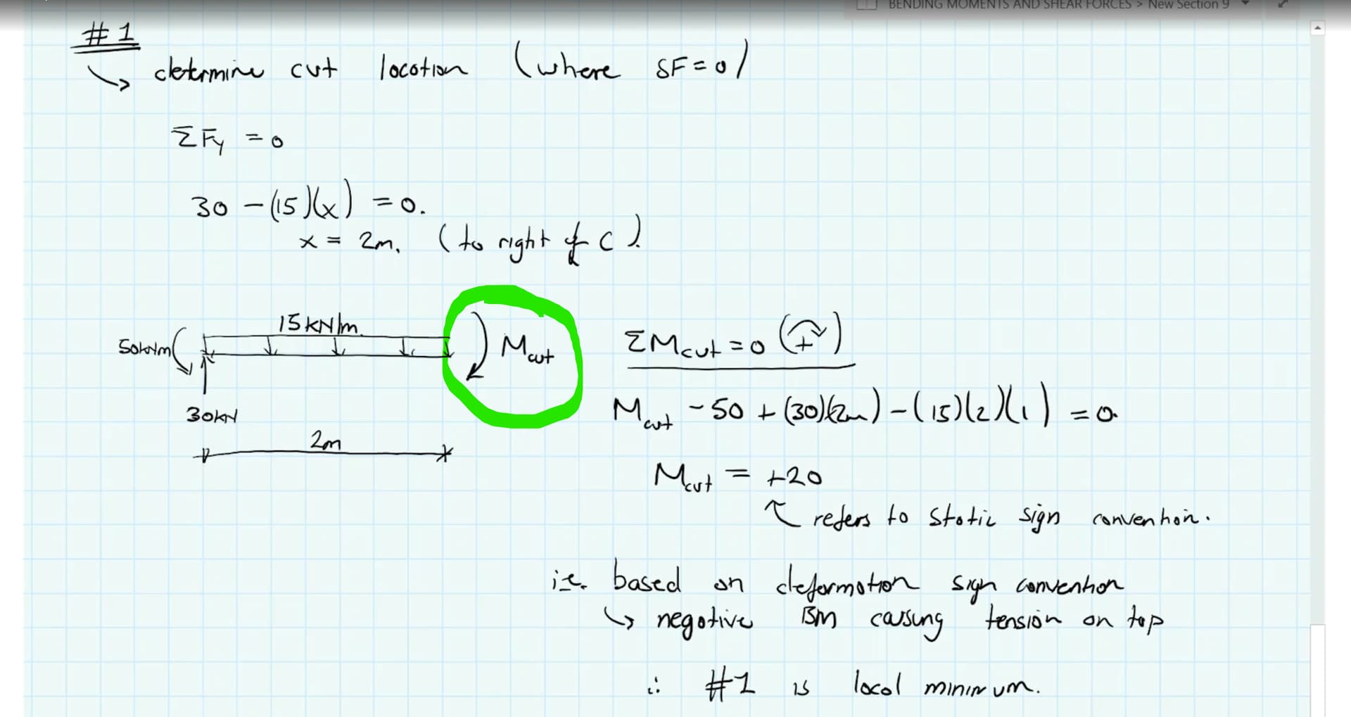
The clockwise internal moment e.g. the 20kNm at 2m from the left tip of the beam (as per your screenshot) is evaluated as a positive number, based on the static sign convention (i.e. clockwise moments defined positive).
However, when it comes to drawing the BMD, we rely on a deformation sign convention that states that bending moments generating tension on the top surface of a horizontal member, are negative (referred to as ‘hogging’). So, the 20kNm appears on the bending moment diagram as a negative 20kNm.
When the bending moment diagram is drawn with the positive vertical axis pointing down, the -20kNm appears to be drawn on the upper or tension face of the beam - fitting in with a common convention of drawing the BM on the tension face of any structure. Sometimes I may omit the negative sign on the diagram since it appears on a diagram, the sign is inferred from the position.
Also note that when we’re evaluating M_cut by evaluating moment equilibrium about the cut, we’re in the static sign convention world - we ignore the deformation sign convention completely and assess the sign of a moment or moment effect of a force, purely based on whether it generated clockwise or counter-clockwise rotation.
Now, if we assume M_cut as clockwise and the number evaluates to a negative - this simply means that we initially assumed the wrong direction and M_cut is actually counter-clockwise.
As a final note - any sign convention is just a set of rules that we establish at the start of an analysis - there is nothing special about them - i.e. you can apply your own rules…the key thing is that you maintain consistency throughout the analysis and that you can interpret (and communicate) the physical meaning of your end result. In practice, common sign conventions are handy, because most people looking at your work will be familiar with ‘the rules of your analysis’ and will be more easily able to interpret your work.
Hope that helps.
Seán
1 Like